Introduction
ClueMaker Configurator is the application used for preparing definitions of the workspace environment for the ClueMaker. The workspace definition contains the setup of data sources, whether the databases or other sources accessed via web service, and definitions of entities and relations between them. Optionally it may include saved searches and reports.
Basic Terms
- Attribute: A database field such as the surname, date, bank account number...
- Entity: In general a set of information related to an object - a person, company, contract, bank account... In the graph, the entities are represented as nodes and specific type of links.
- Node: A key element of the graph that represents a data entity (a person, company, account ...) for which we search for links to its neigbours.
- Link: An expression for connection or relationship between two nodes. It si not necessarily only a technical connection, the link could bear a number of attributes, similarly as the node. (A good example is the bank transaction - the link between two accounts that also contains attributes such as the amount, currency, date ...)
- Label: A text accompanying graphic images. It may contain one or several attributes, a fixed text or combination of both.
Prerequisites
ClueMaker Configurator is used by ClueMaker administrators who must have the information concerning the data sources they plan to use (such as the host and db name, user and password) and knowledge of the structure of data (a database schema in case of db) in the data source they want to use for definition of entities. A basic knowledge of SQL is required.
Workspace Definitions
The workspace definitions are stored either as individual ClueMaker workspace files bearing .sws suffix, or in a database. The workspace file is always selected at the beginning of the ClueMaker session, for which it sets the work environment – available sources of data and entities and links.
Defining New Workspace
Firstly we must define one or more datasources, then we proceed with definitions of data entities and their mappings. Once we have individual entities, we can define links between them.
Workspace creation wizard
To make creating a new workspace an easier task, we've prepared and developed a wizard for guiding you through the process. It tries to analyze the data source provided by you and find candidates for nodes and relations. Thanks to this feature, for creating a new workspace you don't need a thorough knowledge of SQL.
Definition and analysis of a new data source
For the beginning, it's needed to create a new data source that would be then analyzed. You only need to enter the data required to connect to the data source and then run an analysis by clicking the button.
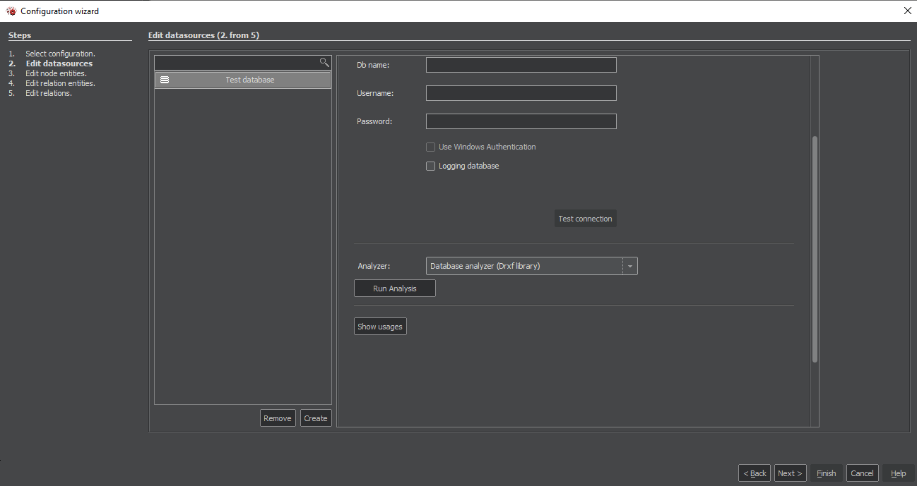
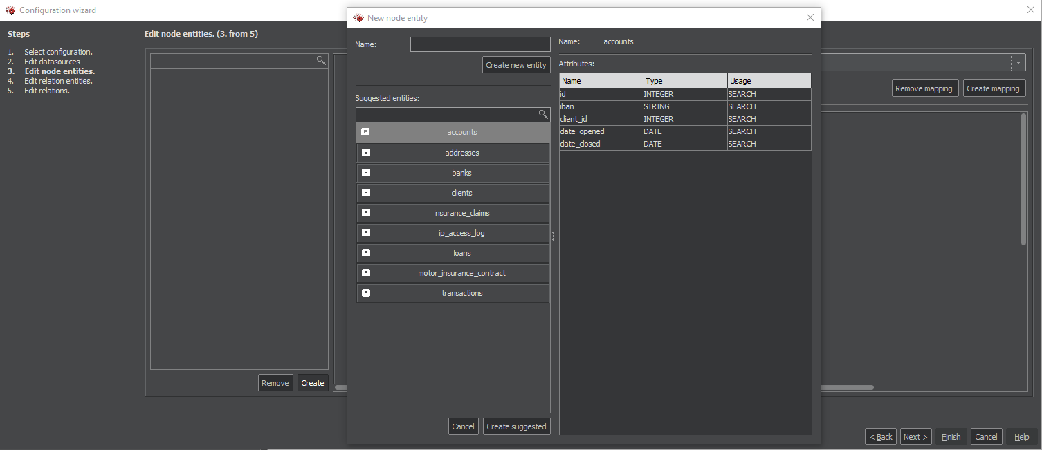
Creating suggested entities and relations
After running the analysis of the data source, in the next steps, it's possible to use suggestions of candidates for nodes and relations by clicking the button Create and choosing the entity in the next window and confirming your selection by clicking the button Create suggested.
New Datasource
In the File menu, select New.
In the Configuration pane, right-click on the Datasource and select New Datasource. This will open the New Datasource tab. On the tab, enter a name for the source and select the type. Then fill in the information for the source. The Figure 1 shows an example of screen with postgres db used as a data source.
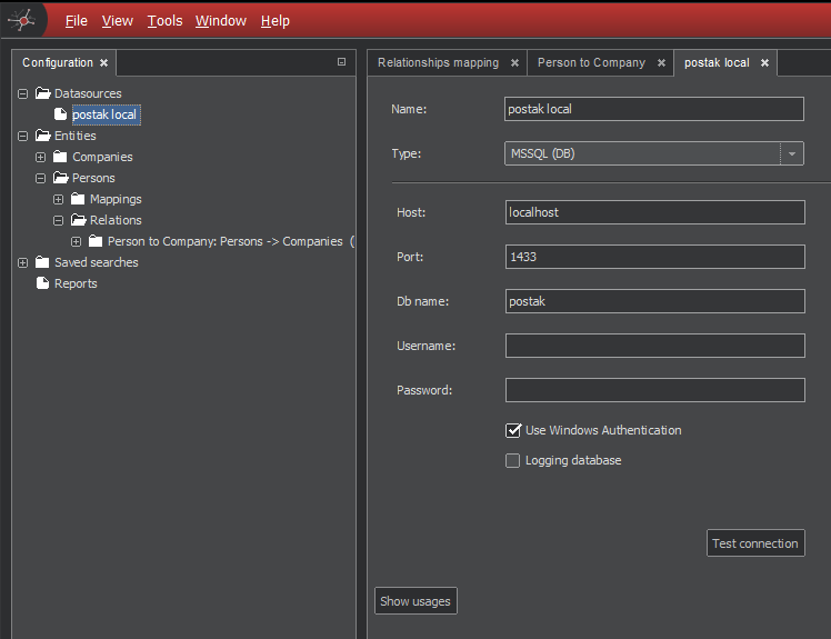
Once configured, test the connection using the Test connection button.
Store the configuration: You can store the complete workspace definition any time by pressing Ctrl-s.
Logging database
It is also possible to use datasource for logging of users' actions (e.g. run of report or search for entity). To enable logging, check the Logging database checkbox. It is required for logging to work properly, that users should have permission to write to the log table. Database should contain the same table, as the table that would be created by script below ran on PostgreSQL database.
create table log (
log_key serial not null,
user_name varchar(100) null,
log_time timestamp not null,
log_level varchar(10) not null,
message varchar(512) not null,
constraint pk_log primary key (log_key)
);
Impala JDBC JARs
If you use an Impala datasource, make sure the following Cloudera JDBC JAR files are available in the installation:
- com.cloudera.impala.jdbc:ImpalaJDBC41:2.6.3.1004 (ImpalaJDBC41.jar)
- com.cloudera.impala.jdbc:hive_metastore:2.5.31 (hive_metastore.jar)
- com.cloudera.impala.jdbc:hive_service:2.5.31 (hive_service.jar)
- com.cloudera.impala.jdbc:ql:2.5.31 (ql.jar)
- com.cloudera.impala.jdbc:TCLIServiceClient:2.5.31 (TCLIServiceClient.jar)
Copy these files to:
cluemaker\modules\ext\eu.profinit.svat.external-impala\com-cloudera-impala-jdbc
under the target application installation directory.
These JAR files are required in both the main ClueMaker application and the ClueMaker Configurator application.
Example for the main application on Windows:
C:\Program Files\ClueMaker\cluemaker\modules\ext\eu.profinit.svat.external-impala\com-cloudera-impala-jdbc
Example for Configurator on Windows:
C:\Program Files\ClueMaker Configurator\cluemaker\modules\ext\eu.profinit.svat.external-impala\com-cloudera-impala-jdbc
If ClassNotFoundException persists after copying the JARs, restart the application and clear its cache/userdir (for example C:\Users\<user>\.cluemakerconfigurator for Configurator, or C:\Users\<user>\.cluemaker for ClueMaker; in some installations it can also be under %APPDATA%).
New Entity
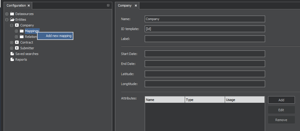
To create a new entity, right-click on the Entity in tree menu. The tab New Entity will appear. You should give the entity a name. You can also fill some attributes now, but the easier way is to do the mapping first and have the attributes filled automatically.
Mapping
As soon as you have created the new entity, it also appears in the tree menu on the left. Let’s expand it, right-click on the Mappings and select Add new mapping.
On the new mapping tab, enter a name for the mapping and select the Datasource.
In the SQL window, write a valid SQL statement that specifies the attributes needed for the entity. Figure 3 shows the simplest form that retrieves all attributes from the table company. Pressing the Load attributes will retrieve the attributes specified by the SQL and place them in the Attributes section.
Note that the column Maps to Attribute shows remarks [Empty], as the retrieved attributes are not yet mapped to the entity 'company'.
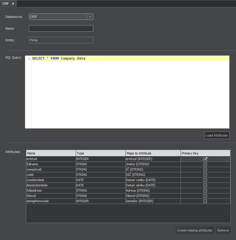
The attributes not needed for your entity can be removed from the mapping by highlighting them and pressing the Remove button.
Now let’s use the the button Create missing attributes. This will create the attributes in the entity ‘company’ with the same name and format as in the data source.
In the column Primary Key is possible to define columns, that are real primary keys to the entityIf the PK is defined, it is possible to run Refresh on this entity in the main application. This will reload the source data again from the original source.
Multiple Mappings
A single entity may have more than one source of data – such as different tables in the same database or tables in different databases. Each source of data will have its mapping. Mappings for the same entity do not need to have the same attributes: a single entity may have some atributes filled from one source and some from another.
Finishing Entity Definition
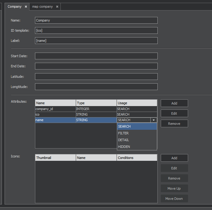
Going back to the entity pane (In our case called 'Company'.), you can change the name and format of each attribute. And you can specify its usage in the ClueMaker, by selecting one of the options from the Usage menu:
- SEARCH - the attribute is searchable at the data source (when loading into ClueMaker) and filterable in ClueMaker.
- FILTER - the attribute is filterable in ClueMaker.
- DETAIL – the attribute is shown only in ClueMaker.
- HIDDEN – a technical attribute, not shown in ClueMaker.
Pay close attention to the following fields:
ID template is the entity ID that plays a key role: when loaded into ClueMaker, all records with the same entity ID will become one instance (a node) of that entity. Each attribute of such entity will contain the first non-empty value encountered when reading the source records. For ID, fill in the attributes in square brackets, as shown on the following figure.
Label designates an optional text to display under the icon. It can be an atribute (in square brackets), a text or a combination of both.
For the timeline functionality it is necessary to define Start Date and End Date. You have to use existing date columns.
For the future we have latitude and longitude values. In next versions we plan to implement GIS features to ClueMaker so you will be then able to put entities to proper places on map.
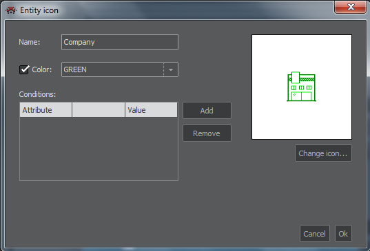
You should also select an icon that will represent the entity in ClueMaker. The Add button beside the Icon window will open the dialog Entity Icon, shown on Figure 5. The Change Icon button lets you to select the icon from the list. You can give the icon a name and select its colour.
Using multiple icons: ClueMaker can show different icons, or icon colours to diferentiate entitties based on their key features, such as the status flag, certain level of revenue etc. For such case we define several icons for the entity and for each icon we specify one or more conditions. Figure 6 shows a conditions for Contract icons with different colours.
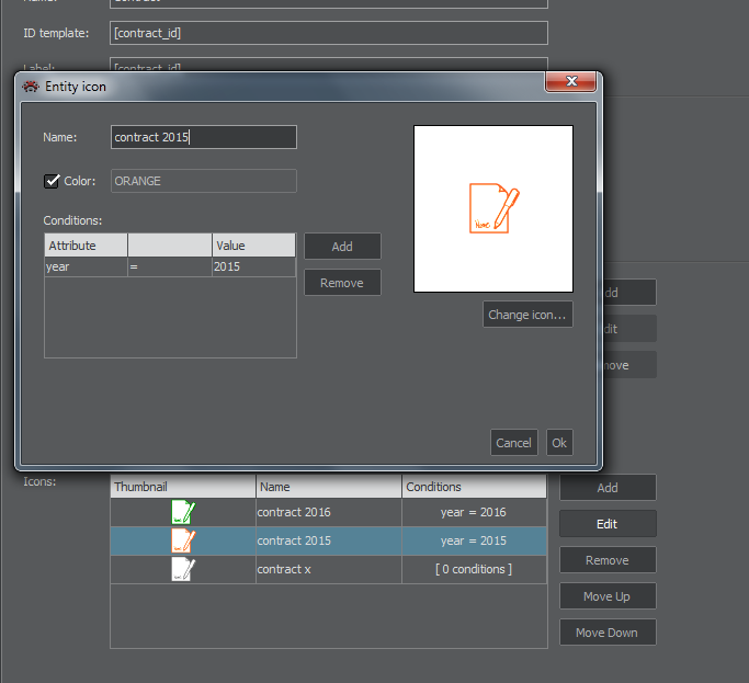
When assigning the icon to the entity instance, ClueMaker will evaluate conditions in the icon list in top-down order.
Defining Relations
To define a new relation, right-click on the Relations and select one of two options.
1:N Relation
This type covers one-to-many and one-to-one relationships. On the New relation tab you can give the relation a name. You must specify the source and target entities and, in the Conditions section, the attributes that link them.
To add more linking conditions, use the + sign
To remove the condition, use the garbage can sign on the right.
Label designates an optional text to display for the link. It can be an atribute (in square brackets), a text or a combination of both.
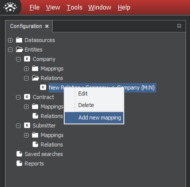
M:N Relation
This denotes the many-to-many relationship. In the database, such a relationship is represented by the cross-reference or junction table, therefore it requires the mapping of that table.
Once you create the New relation … M:N, right-click on it and select Add new mapping.
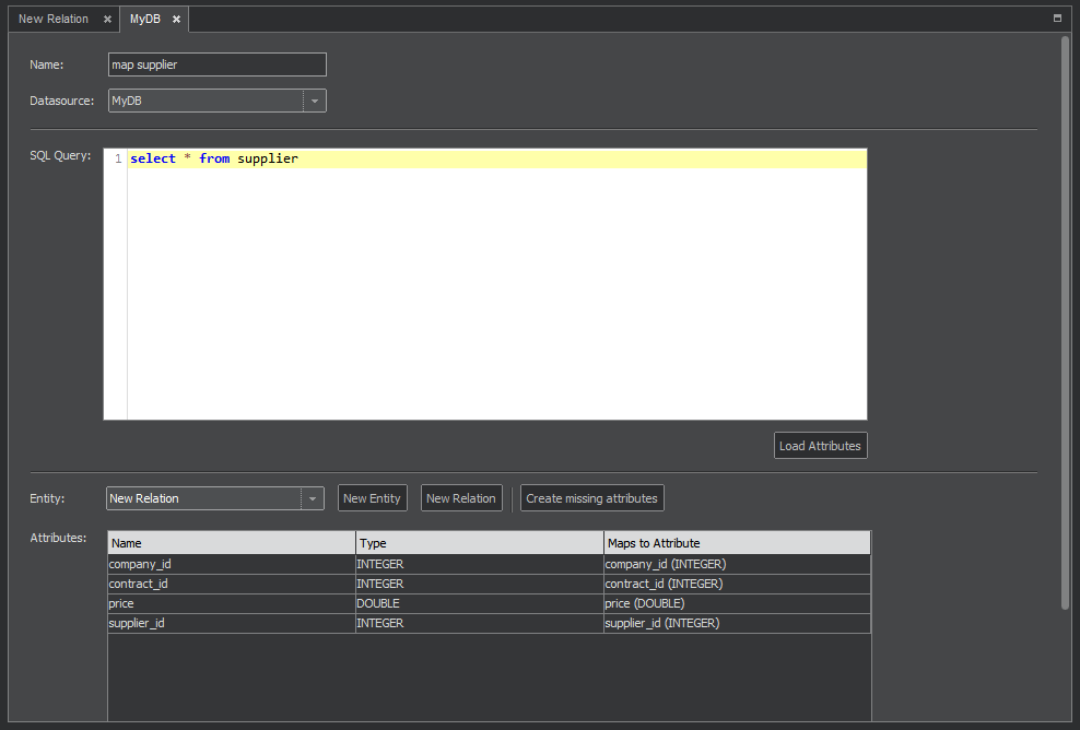
In our example, we’ll create a relation between entities 'contract' and 'company' using the junction table 'supplier'. Its mapping is shown on Figure 9. For details how to set up the mapping, see the Mapping section.
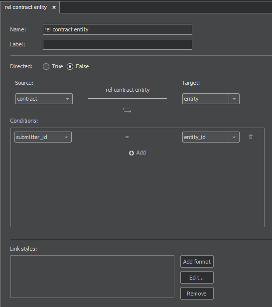
Now return to the New relation pane, where the Attributes section already shows the attributes from the mapping of the junction table. Complete the definition of relation by giving it a name, selecting Directed: True/False and specifying the source and target entities (In our example 'company' and 'contract'.)
In the Conditions section, under the name of the source entity, we select the attributes that link the source entity with the junction table. The same will be done for the link between the junction table and target entity on the right side of the section.
We still need to pay close attention to the following fields:
ID template shall be a unique identifier for the link – an attribute (in square brackets) or a combination of attributes, otherwise the links may not display in the graph correctly. Incorrect definition can lead to loss of relations, so only one relation instead of more will be displayed. Our example uses the attribute ‘Id’ from the junction table.
Label designates an optional text to display for the link. It can be an atribute (in square brackets), a text or a combination of both.
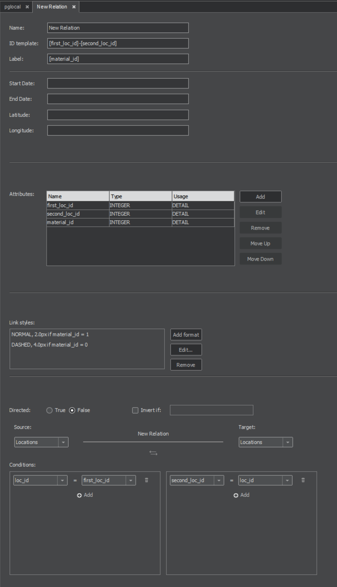
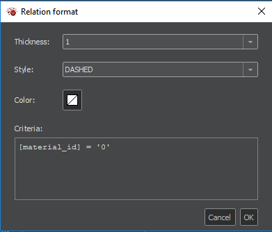
Link styles
You can define link styles for relations, e.g. their thickness, type of line or its colour. These styles are applied according to given criteria. The first style whose criteria are met is used. You can define criteria like shown in Figure 10.1 - name of attribute of interest enclosed in square brackets and desired value enclosed in single quotation marks. Other operators, that can be used instead of equals (=) are less/greater than (<, >, <=, >=) or CONTAINS (checks if string attribute contains given substring). With operators IN and NOT IN followed by comma-separated list of values in parentheses is possible to check, whether attribute contains (or doesn't contain any) value from list. You can use multiple conditions and chain them intuitively either with AND and OR keywords and parentheses. You can negate the criteria too, by using keyword NOT followed by criteria in parentheses.
Reports
ClueMaker can execute reports stored in the workspace. The reports are set up with the help of ClueMaker Configurator using steps described below.
Creating Report
In the Configuration pane, right-click on the Reports and select New Report to get the New Report window shown on the next figure.
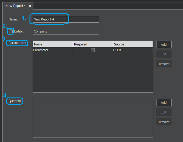
1. In the Name fill the name that will identify the report in ClueMaker.
2. The checkmark Entity is essential for distinguishing two types of reports:
- Reports associated with an entity will have the Entity checkmark checked and the entity selected. In ClueMaker,these reports are called from the graph and can be executed only when at least one instance of the select entity exists in the graph/data table. They are usually, but not necessarily, linked to entities in the graph with the help of predefined parameters.
- Reports without the graph entity association will have the checkmark unchecked. In ClueMaker, these reports are called from the top menu Tools>Execute report. The selection of data can be controlled with the help of parameters that require an input from a user.
3. In the Parameters section you can define one or more parameters that control the report. See Report Parameters below.
4. In the Query section you define one or more queries that will generate the report. For details refer to Report Query below.
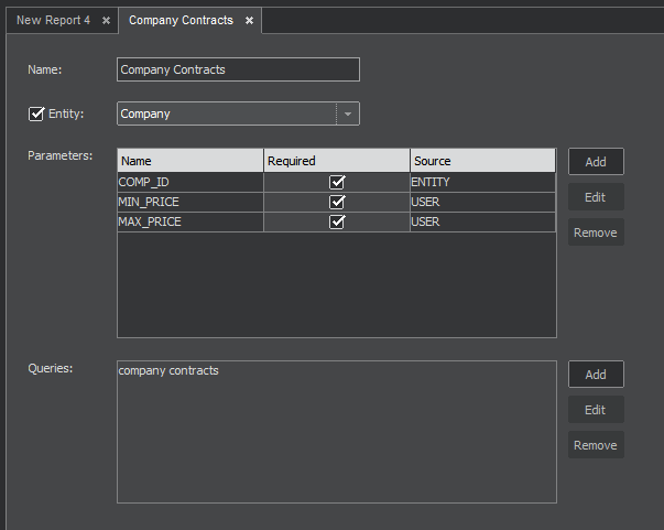
The next figure shows the report window with data already filled.
Report Parameters
Use the Add button to create a new parameter.
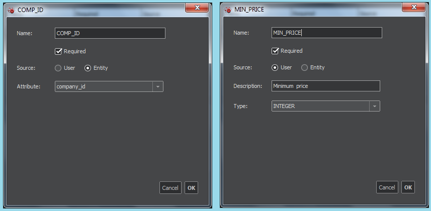
Highlighting the parameter name in the Parameters section and pressing the Edit button will open the Parameter window. Here we specify:
- The Name that will be used in the appropriate place in the report query.
- The flag Required marks the fields that must be filled with a value.
- The choice of Source User/Entity: The parameters marked as Entity will take the value(s) from the designated attribute of the entity(ies) selected in the graph prior to the execution. The parameters marked as User will prompt the user for an input.
- For the Entity source, specify the entity Attribute used as a source of data.
- For the User source, specify Type of data and in Description enter the string for the prompt.
Internal report parameters
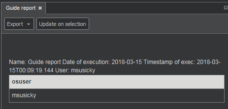
Application ClueMaker has included following variables for your comfort:
- report_name - Name of the report
- report_date - Execution date
- report_datetime - Execution datetime
- report_osuser - Name of the system in OS
Report Query Definition
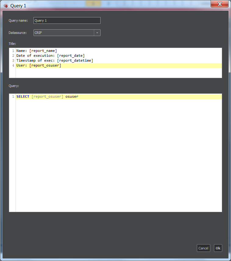
Clicking Add beside the Query section will open the New Query window, whose example is on the next figure.
- Enter the name of query and select its data source.
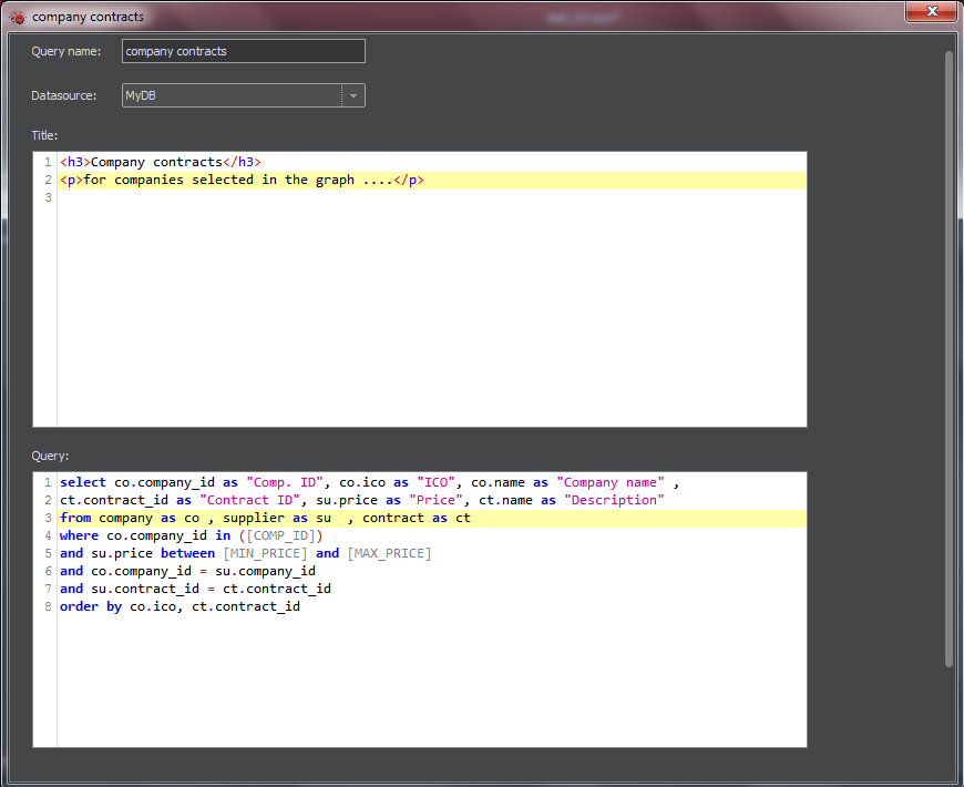
- In Title section, you can enter a plain text of the title or text formatted with the help of HTML tags.
- In the Query section, enter a valid SQL code. If there are parameters set up for the report , the sql shall include them. The parameter names are written in square brackets and must be used in accordance with the SQL syntax for the particular database.
Important note: the parameters that may include multiple values – typically the parameters where the entity is the source of data – are parsed as the comma separated lists and must be used accordingly. For example if the parameter COMPID contains numbers 125, 155, 268 , then the statement:
select * from company where company_id = [COMPID]
...will fail because the condition is parsed as ... company_id = 125, 155, 268
The proper syntax is:
select * from company where company_id in ( [COMPID] )
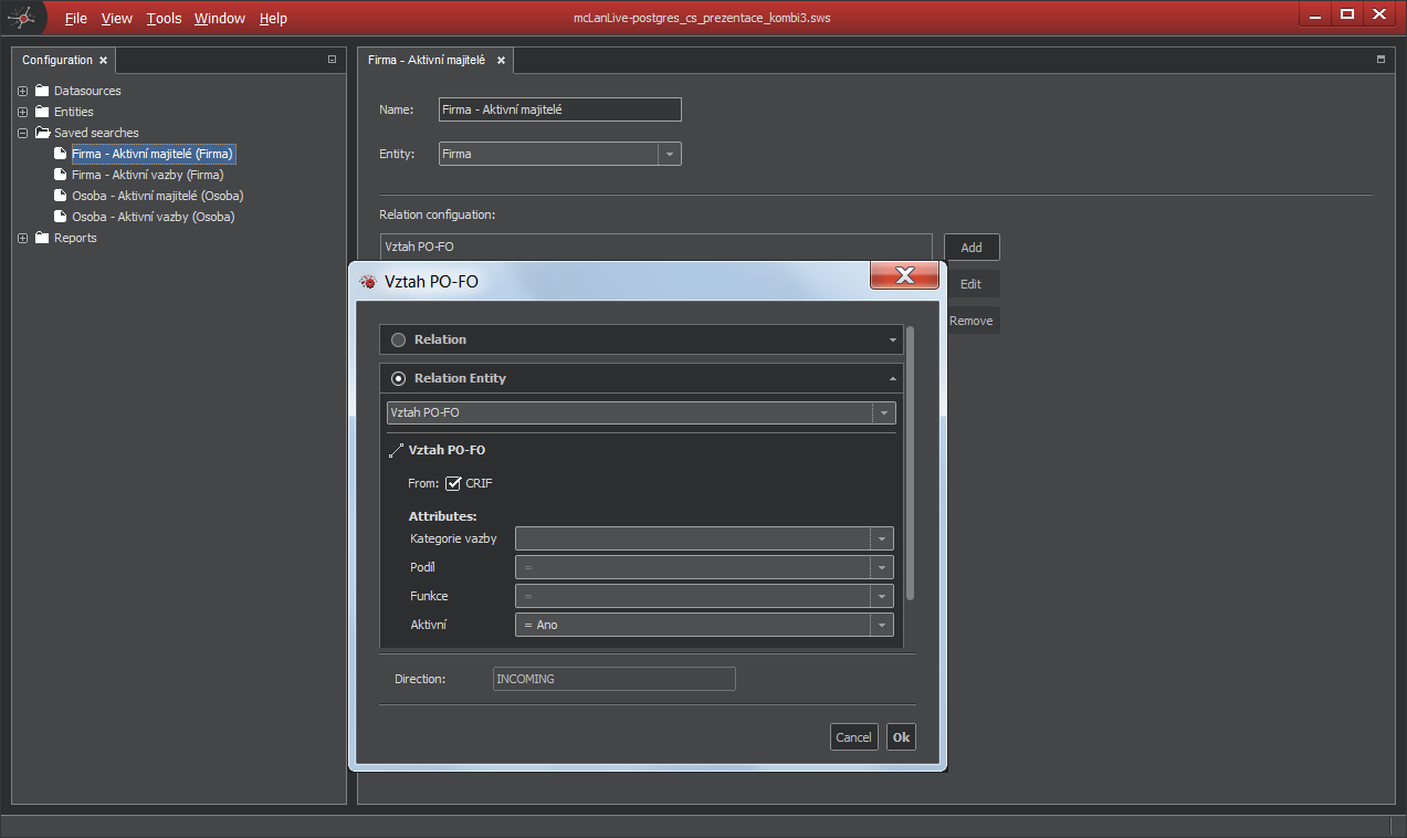
Saved search
If you have often searched relations, you can predefine Saved search. The principle is quite easy, you have to define searched relations and entities. In the Configurator you can define for every entity up to 255 Saved searches.
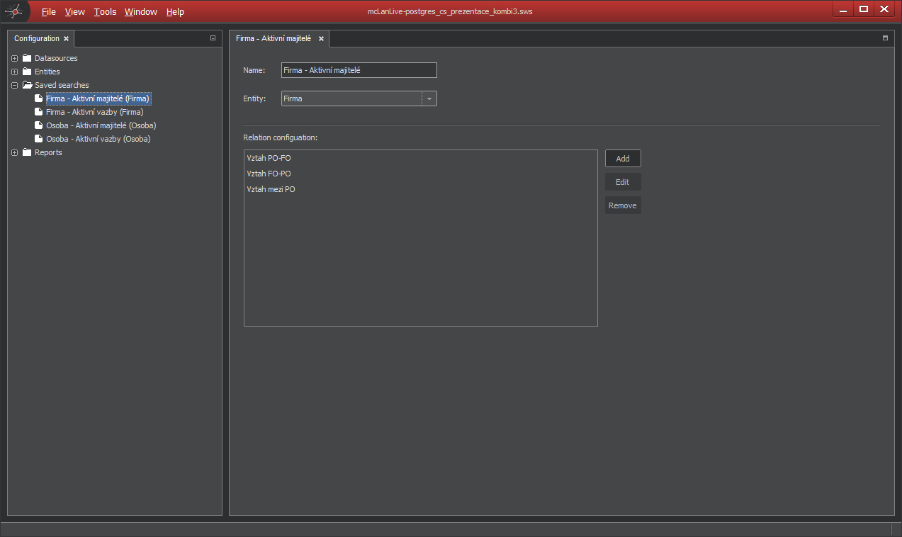
Saved search configuration
In the Configuration pane, right-click on the Saved search and select New Saved search to get new empty Saved search.
And if you create new Saved search:
When you save your workspace, you can then find your Saved search in the context menu. This is very powerful functionality when you know, what is the most searched by your users.